Power Engineer with 15+ years of experience in pulp and paper, power generation, and oil & gas processing facilities. Operating Manager at Power Engineering 101, helping students prepare for Canadian power engineering certification exams.
This post we will be covering how to determine the minimum required thickness of noncircular unstayed flat heads and covers. We will review the formula(s), define the various variables in the formulas, and review practice questions to reinforce the material covered. If you haven’t already, make sure you review the following posts as it will help you understand the material below.
How To: Determine The Minimum Required Thickness Of Circular Unstayed Flat Heads And Covers
All referenced page numbers are from the 2007 ASME Boiler & Pressure Vessel Code
Formula
PG-31.3.3 page 15 Flat unstayed heads, covers, or blind flanges may be square, rectangular, elliptical, obround, segmental, or otherwise noncircular. There required thickness shall be calculated by the following equation.
Minimum Thickness Formula:
 (3)
(3)
where
![]() (4)
(4)
with the limitation that Z need not be greater then 2.5.
It is important to note that Equation (3) does not apply to noncircular heads, covers, or blind flanges attached by bolts causing a bolt edge moment [Fig. PG-31, illustration (j) and (k)].
Maximum Allowable Working Pressure Formula:
The minimum required thickness formula above can be transposed to determine the MAWP formula for noncircular unstayed flat heads and covers.
![]()
The above formula is not provided in the 2007 ASME Boiler & Pressure Vessel Code
Formula Variables
The variables used in the formulas provided above to determine the minimum required thickness of noncircular unstayed flat heads and covers are defined in PG-31.2 page 15 as follows:
C = A factor depending on the method of attachment of head and on the shell, pipe, or header dimensions, and other items listed in PG-31.4 below, dimensionless. The factors for welded covers also include a factor of 0.667 that effectively increases the allowable stress for such construction to 1.5S.
D = long span of noncircular heads or covers measured perpendicular to short span
d = Diameter, or short span, measured as indicated in Fig. PG-31
P = Maximum allowable working pressure
S = Maximum allowable stress value, psi (kPa), using values given in Table 1A of Sections II, Part D
t = Minimum required thickness of flat head or cover
Z = A factor for noncircular heads and covers that depends on the ratio of short span to long span, as given in PG-31.3, dimensionless.
How To: Determine The Minimum Required Thickness Of Noncircular Unstayed Flat Heads And Covers Questions
Note: All code questions are to be calculated in (mm) and (MPa) unless otherwise stated. Convert accordingly and properly before the calculation.
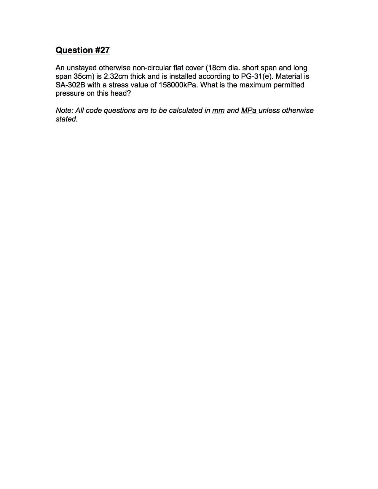
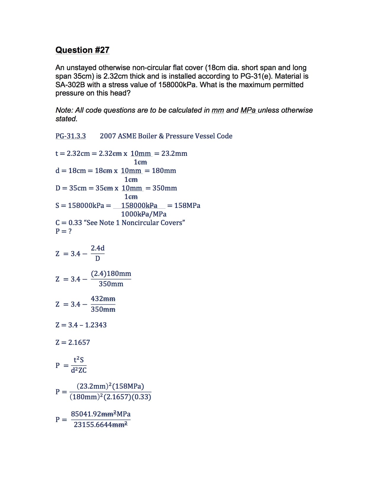
Question #27
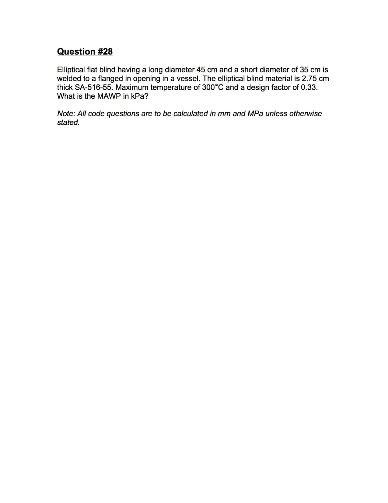
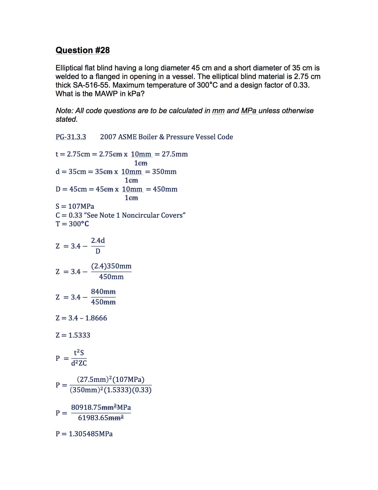
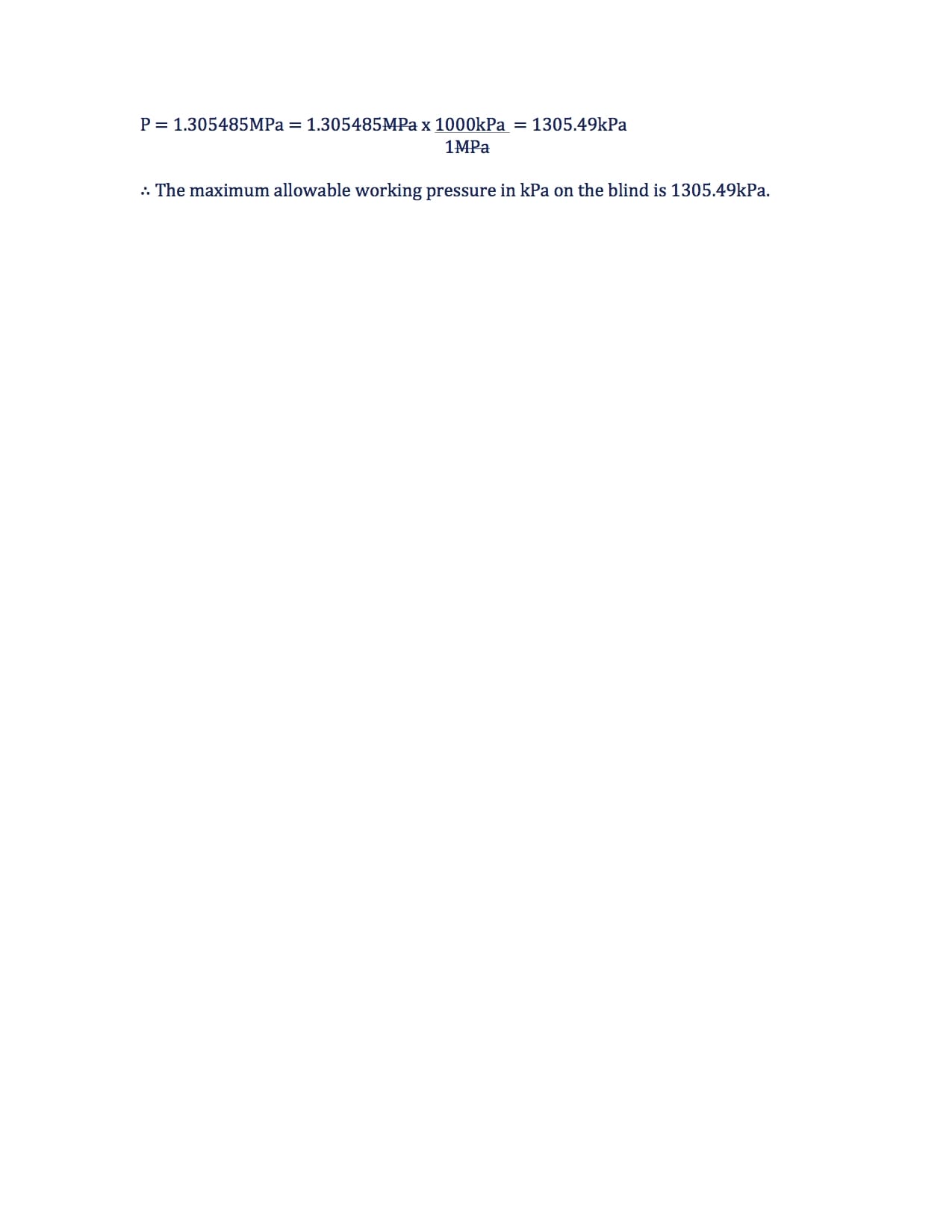
Question #28
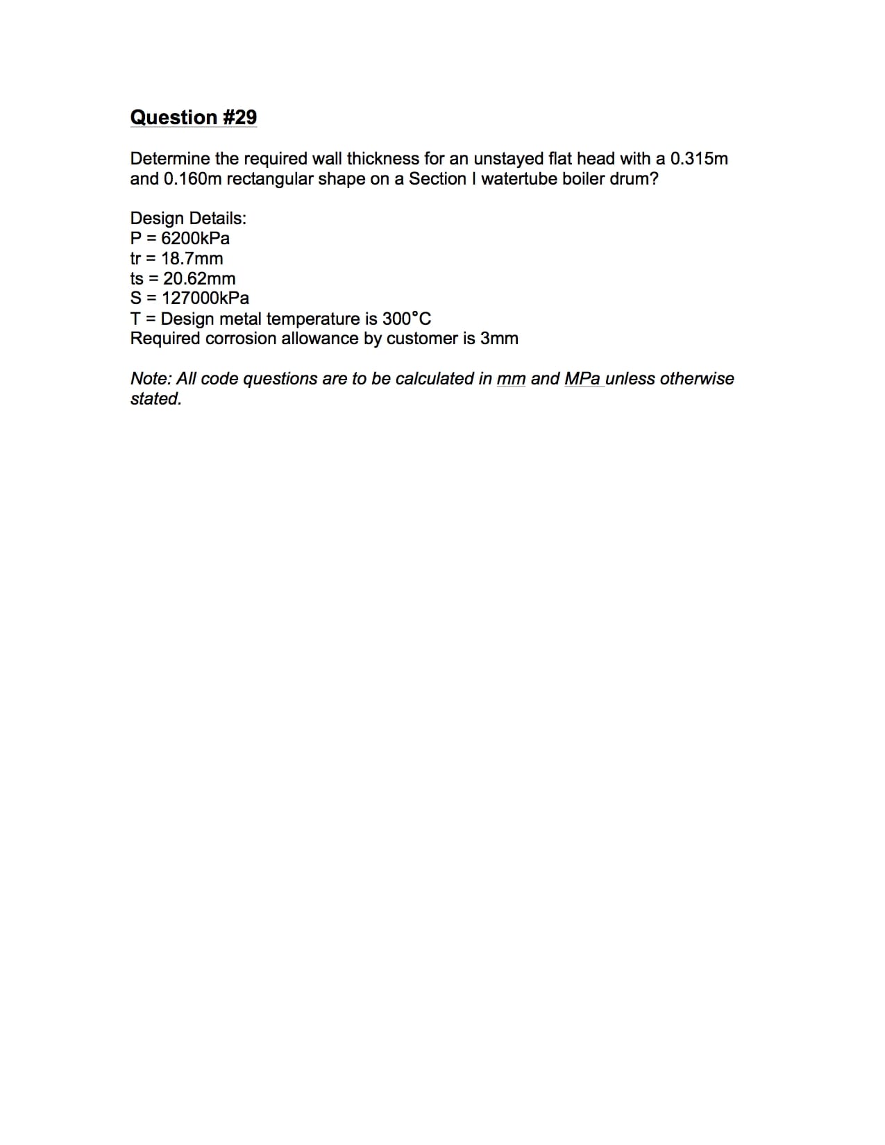
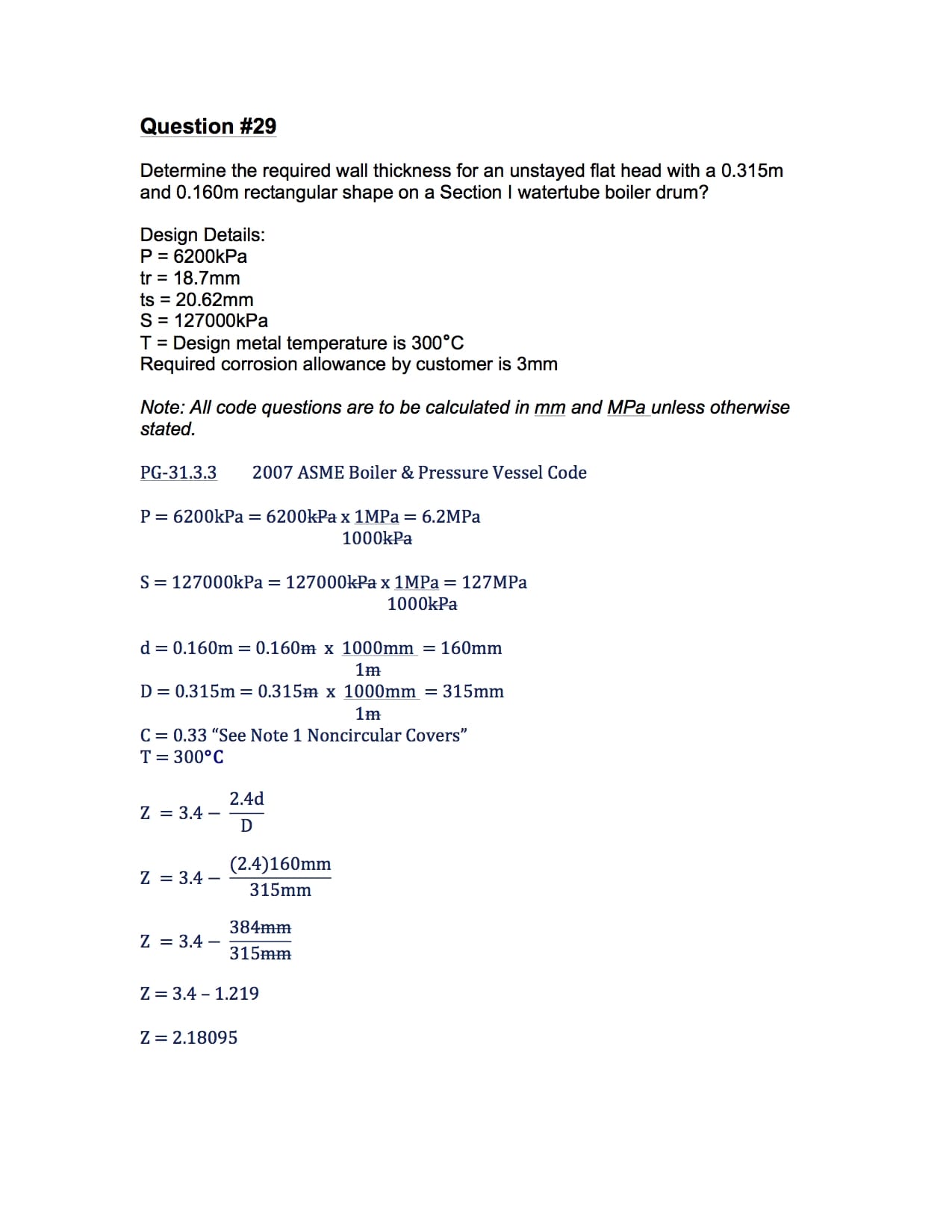
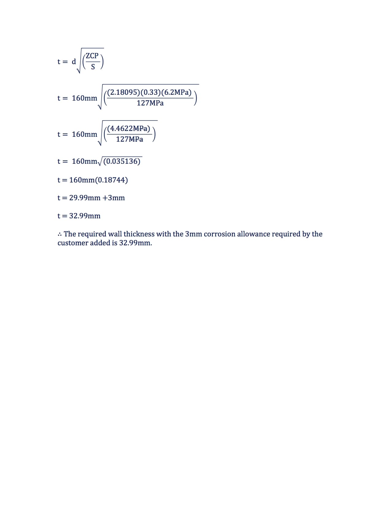
Question #29
2A1 Power Engineering Exam Study Material
Summary
Hopefully the examples provided help you understand how to calculate the minimum required thickness of noncircular unstayed flat heads and covers. If you have additional questions, feedback, or ideas to improve the content provided please let me know in the comment section below.
Thank you,
Power Engineering 101