Power Engineer with 15+ years of experience in pulp and paper, power generation, and oil & gas processing facilities. Operating Manager at Power Engineering 101, helping students prepare for Canadian power engineering certification exams.
This post we will be learning how to determine the minimum required thickness of circular unstayed flat heads and covers when attached by bolts. We will review the formula, define the various variables in the formula and review a practice question to reinforce the material covered. If you haven’t already, make sure you review How To: Determine The Minimum Required Thickness Of Circular Unstayed Flat Heads, Covers before tackling this post.
All referenced page numbers are from the 2007 ASME Boiler & Pressure Vessel Code
Formula
PG-31.3.2 page 15 The minimum required thickness of flat unstayed circular heads, covers, and blind flanges shall be calculated with the following equation except when the head, cover, or blind flange is attached by bolts causing an edge moment [Fig. PG-31, illustrations (j) and (k)] in which case the thickness shall be calculated by the following equation:
Minimum Required Thickness Formula
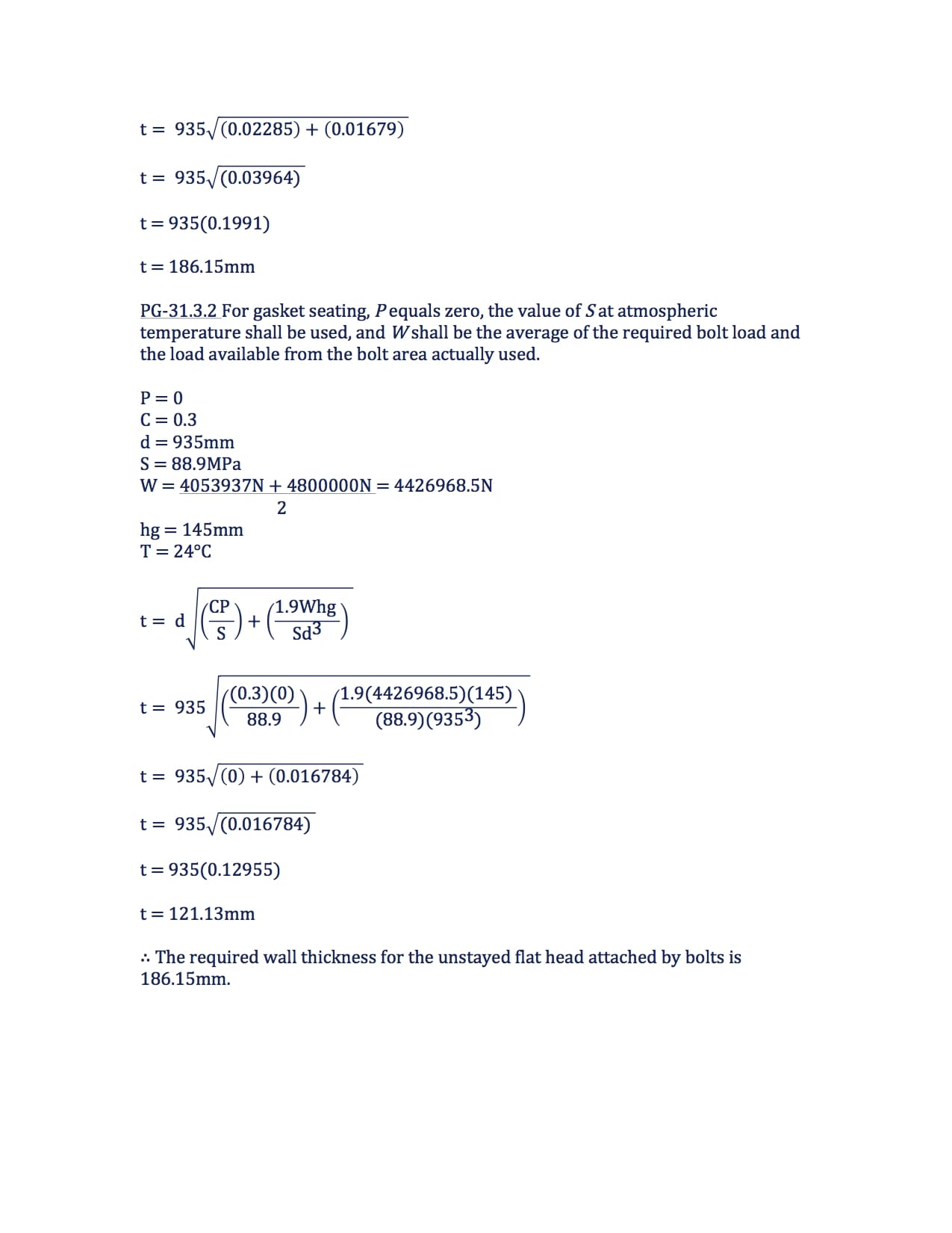
PG-31.3.2 says when using the above equation or equation (2) in your code book the thickness t shall be calculated for both design conditions and gasket seating, and the greater of the two values shall be used. For design conditions, the value P shall be the maximum allowable working pressure, the value S at design temperature shall be used, and W shall be the sum of the bolt loads required to resist the end pressure load and to maintain tightness of the gasket. For gasket seating, P equals zero, the value S at atmospheric temperature shall be used, and W shall be the average of the required bolt load and the load available from the bolts actually used.
Formula Variables
The variables used in the formulas provided above to determine the minimum required thickness of circular unstayed flat heads and covers when attached by bolts are defined in PG-31.2 page 15 as follows:
C = A factor depending on the method of attachment of head and on the shell, pipe, or header dimensions, and other items listed in PG-31.4 below, dimensionless. The factors for welded covers also include a factor of 0.667 that effectively increases the allowable stress for such construction to 1.5S.
d = Diameter, or short span, measured as indicated in Fig. PG-31
P = Maximum allowable working pressure
S = Maximum allowable stress value, psi (kPa), using values given in Table 1A of Sections II, Part D
t = Minimum required thickness of flat head or cover
hg = Gasket moment, arm equal to the radial distance from the center line of the bolts to the line of the gasket reaction, as shown in Fig. PG-31, illustrations (j) and (k)
W = Total bolt load, as further defined in PG-31.3.2
[table id=1 /]
How To: Determine The Minimum Required Thickness Of Circular Unstayed Flat Heads And Covers When Attached By Bolts Questions
Note: All code questions are to be calculated in (mm) and (MPa) unless otherwise stated. Convert accordingly and properly before the calculation.
Question #26
Summary: Circular Unstayed Flat Heads And Covers When Attached By Bolts
I have found the following key points important when completing how to determine the minimum required thickness of a circular unstayed flat heads and covers attached by bolts calculations:
- The thickness t shall be calculated for both design conditions and gasket seating, and the greater of the two values shall be used
- For design conditions, the value P shall be the maximum allowable working pressure, the value S at design temperature shall be used, and W shall be the sum of the bolt loads required to resist the end pressure load and to maintain tightness of the gasket
- For gasket seating, P equals zero, the value S at atmospheric temperature shall be used, and W shall be the average of the required bolt load and the load available from the bolts actually used.
Are you following Power Engineering 101 on Twitter?