Power Engineer with 15+ years of experience in pulp and paper, power generation, and oil & gas processing facilities. Operating Manager at Power Engineering 101, helping students prepare for Canadian power engineering certification exams.
When completing ASME code calculations involving cylindrical components you will be required to know how to determine the maximum allowable working pressure of piping.
All referenced page numbers are from the 2007 ASME Boiler & Pressure Vessel Code.
Formula
To determine the maximum allowable working pressure of piping during different operating conditions you can use the formula contained within ASME Boiler & Pressure Vessel Code PG-27 Cylindrical Components Under Internal Pressure page 10. Specifically, PG-27.2.2 page 10
PG-27.2.2 Piping, Drums, and Headers. (based on strength of weakest course) It is important to remember any cylinder with an outside diameter less then 125mm is to be considered tubing and the equation provided in PG-27.2.1 page 8 should be used.
PG-27.2.2 Formula to calculate the maximum allowable working pressure for piping:
Outside Diameter Equation
![]()
Inside Radius Equation
![]()
Formula Variables
The symbols used within the PG-27 formulas are contained within paragraph PG-27.3 page 10 and are defined as follows:
C = Minimum allowance for threading and structural stability (mm) (PG-27.4, note 3) page 11
D = Or O.D. is Outside diameter of cylinder (mm) “In this case piping”
E = Efficiency of longitudinal welded joints or of ligaments between openings, whichever is lower (the values allowed for E are listed in PG-27.4, note 1) page 11
e = Thickness factor for expanded tube ends (mm) (see PG-27.4, note 4) page 11
P = Maximum allowable working pressure “Gauge Pressure” (MPa) (see PG-21, refers to gauge pressure)
R = Inside radius of cylinder (mm) “In this case piping”
S = Maximum allowable stress value at the operating temperature of the metal (Section II, Part D, Table 1A. See PG-27.4, note 2) page 11. It is important when determining the maximum allowable stress value to check (PG-6 plate materials) page 4 and (PG-9 boiler tube materials) page 5 before starting calculations as this information will determine the correct stress table to use by indicating whether the material is carbon steel or an alloy steel.
t = minimum required thickness (mm) (see PG-27.4, note 7) page 12
y = temperature coefficient (see PG-27.4, note 6) page 11
[table id=1 /]
How To: Determine The Maximum Allowable Working Pressure Of Piping Questions
Note: All code questions are to be calculated in (mm) and (MPa) unless otherwise stated. Convert accordingly and properly before the calculation.
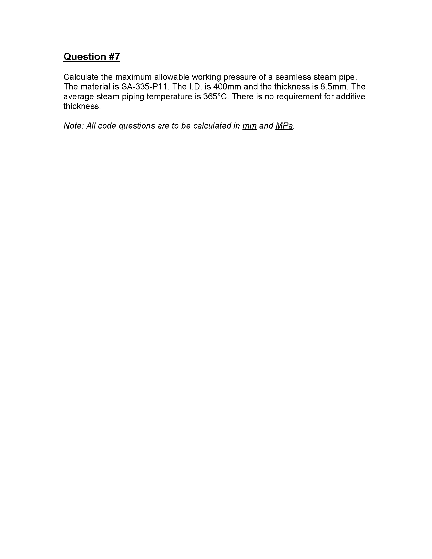
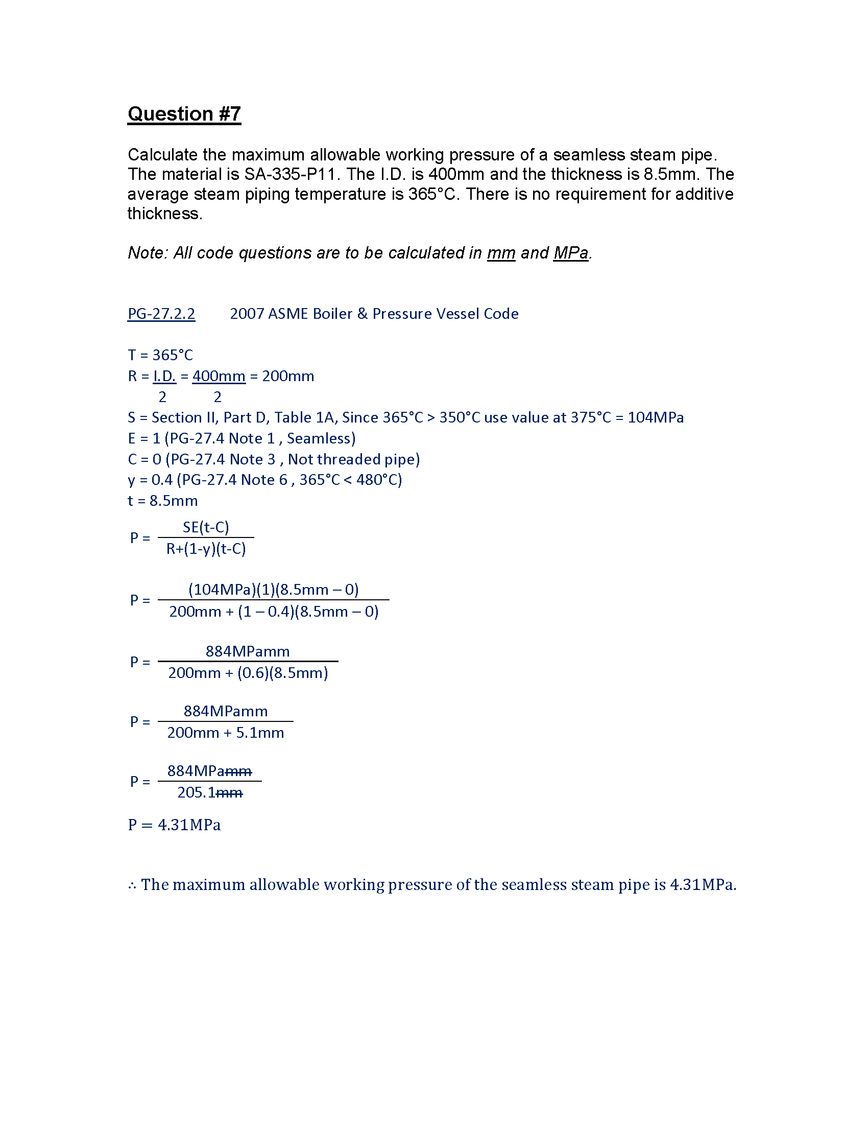
Question #7
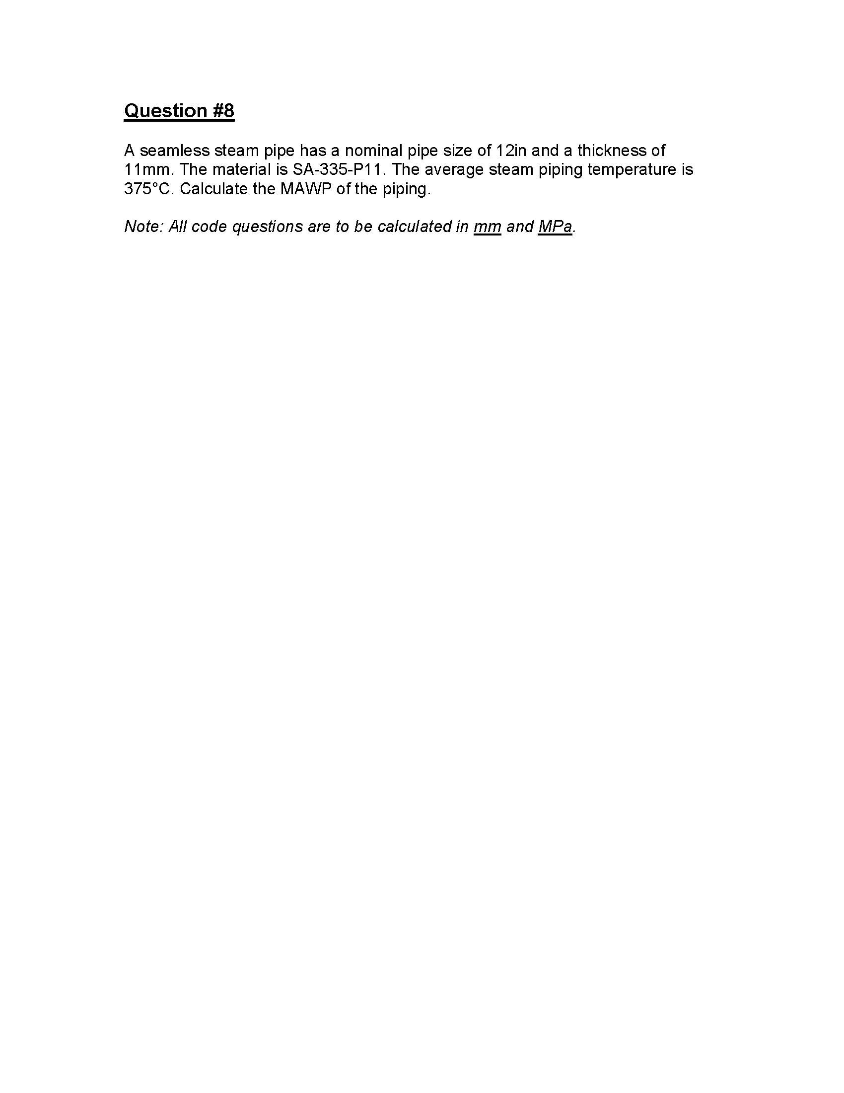
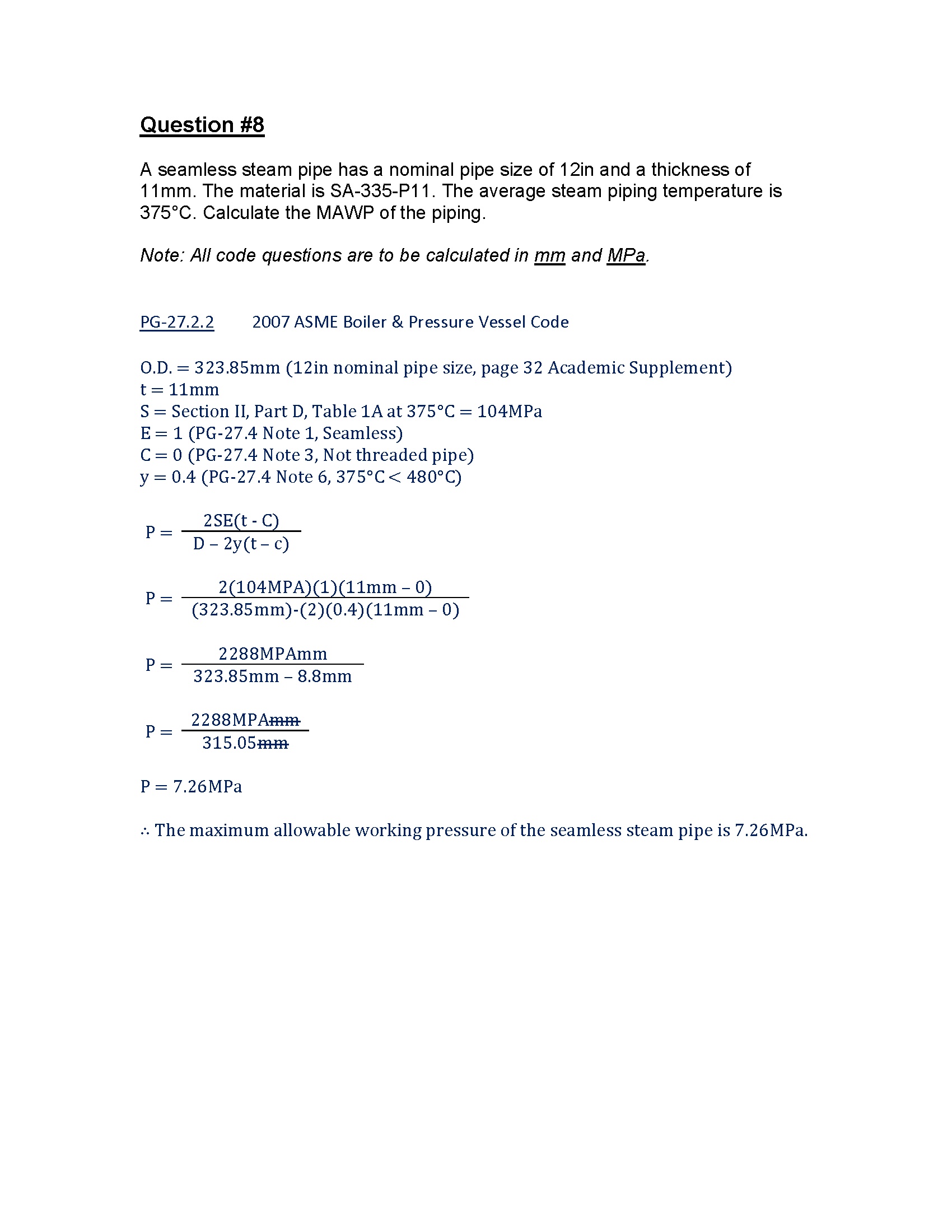
Question #8
2A1 Power Engineering Exam Study Material
How To: Determine The Maximum Allowable Working Pressure Of Piping Summary
Did the practice questions provided help you understand how to calculate the maximum allowable working pressure for piping better? Let me know in the comment section below.
If you are studying for 2A1 and like what you see so far, make sure you join Power Engineering 101 at the top right to be informed when new material is posted.
Thank you,
Power Engineering 101